
embedded 原文存档
stm32L476基于platformIO控制LORA芯片SX1280 SPI通信
硬件:
- (stm32L476)st nucleo L476RG:链接:https://www.st.com/zh/evaluation-tools/nucleo-l476rg.html
- (sx1280芯片)ebyte E28 2G4M20S:链接:https://www.ebyte.com/product-view-news.aspx?id=304
- 自制SPI板-arduino接口
- 3D打印外壳:需要土八螺母(M2,长4mm)
软件:
- vscode
- platformIO+arduino框架
- 库:jgromes/RadioLib@^6.3.0
引脚接口:
- NSS pin: PA4
- DIO1 pin: PA9
- NRST pin: PB0
- BUSY pin: PA1
- SPI MOSI:PA7
- SPI MISO:PA6
- SPI SCK:PA5
- TX EN:PB8
- RX EN:PB9
- led1:PC0
- led2:PC1
主测试代码
使用LORA_MASTER切换发射端还是接收端
`#include <Arduino.h> #include <SPI.h> #include <EEPROM.h> #include <RadioLib.h> //1=TX,0=RX #define LORA_MASTER 1 #if LORA_MASTER==1 /************block send***************/ SX1280 radio = new Module(PA4, PA9, PB0, PA1); void setup() { Serial.begin(115200); Serial.print(F("[SX1280] Initializing ... ")); int state = radio.begin(2412, 1625, 10, 5); if (state == RADIOLIB_ERR_NONE) { Serial.println(F("success!")); } else { Serial.print(F("failed, code ")); Serial.println(state); while (true); } radio.setRfSwitchPins(PB9, PB8); } int count = 0; void loop() { Serial.print(F("[SX1280] Transmitting packet ... ")); String str = "Hello World! #" + String(count++); int state = radio.transmit(str); // you can also transmit byte array up to 256 bytes long /* byte byteArr[] = {0x01, 0x23, 0x45, 0x56, 0x78, 0xAB, 0xCD, 0xEF}; int state = radio.transmit(byteArr, 8); */ if (state == RADIOLIB_ERR_NONE) { Serial.println(F("success!")); } else if (state == RADIOLIB_ERR_PACKET_TOO_LONG) { Serial.println(F("too long!")); } else { Serial.print(F("failed, code ")); Serial.println(state); } delay(1000); } /************************block send***************************/ #else /************************block REV***************************/ SX1280 radio = new Module(PA4, PA9, PB0, PA1); void setup() { Serial.begin(115200); Serial.print(F("[SX1280] Initializing ... ")); int state = radio.begin(2412, 1625, 10, 5); if (state == RADIOLIB_ERR_NONE) { Serial.println(F("success!")); } else { Serial.print(F("failed, code ")); Serial.println(state); while (true); } radio.setRfSwitchPins(PB9, PB8); } void loop() { Serial.print(F("[SX1280] Waiting RXRXRXRXRXRXRX ... ")); // you can receive data as an Arduino String String str; int state = radio.receive(str); // you can also receive data as byte array /* byte byteArr[8]; int state = radio.receive(byteArr, 8); */ if (state == RADIOLIB_ERR_NONE) { // packet was successfully received Serial.println(F("success!")); // print the data of the packet Serial.print(F("[SX1280] Data:\t\t")); Serial.println(str); // print the RSSI (Received Signal Strength Indicator) // of the last received packet Serial.print(F("[SX1280] RSSI:\t\t")); Serial.print(radio.getRSSI()); Serial.println(F(" dBm")); // print the SNR (Signal-to-Noise Ratio) // of the last received packet Serial.print(F("[SX1280] SNR:\t\t")); Serial.print(radio.getSNR()); Serial.println(F(" dB")); // print the Frequency Error // of the last received packet Serial.print(F("[SX1280] Frequency Error:\t")); Serial.print(radio.getFrequencyError()); Serial.println(F(" Hz")); } else if (state == RADIOLIB_ERR_RX_TIMEOUT) { // timeout occurred while waiting for a packet Serial.println(F("timeout!")); } else if (state == RADIOLIB_ERR_CRC_MISMATCH) { // packet was received, but is malformed Serial.println(F("CRC error!")); } else { // some other error occurred Serial.print(F("failed, code ")); Serial.println(state); } } /************************block REV***************************/ #endif`遇到的坑:
1,引脚设置
`// NSS pin: PA4 // DIO1 pin: PA9 // NRST pin: PB0 // BUSY pin: PA1 SX1280 radio = new Module(PA4, PA9, PB0, PA1);`2,stm32duino的默认设置
spi默认就是PA5 PA6 PA7,不需要设置
3,如果自定义SPI引脚
`// MOSI MISO SCLK SSEL SPIClass myspi2(PA_7, PA_6, PA_5); SPISettings spiSettings(2000000, MSBFIRST, SPI_MODE0); SX1280 radio = new Module(PA4, PA9, PB0, PA1, myspi2, spiSettings);`4,lora设置
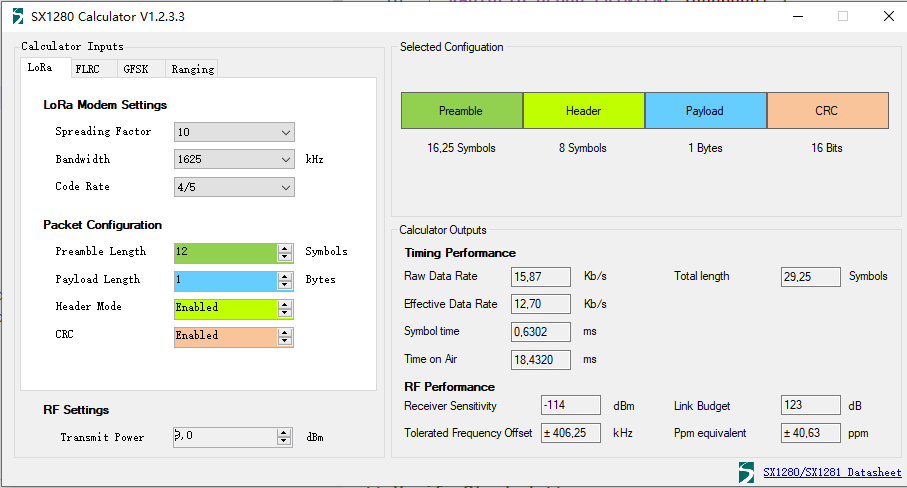
`//param freq Carrier frequency in MHz. Defaults to 2400.0 MHz. //param bw LoRa bandwidth in kHz. Defaults to 812.5 kHz. //param sf LoRa spreading factor. Defaults to 9. //param cr LoRa coding rate denominator. Defaults to 7 (coding rate 4/7). //param syncWord 2-byte LoRa sync word. Defaults to 0x12 //param pwr Output power in dBm. Defaults to 10 dBm. //param preambleLength LoRa preamble length in symbols. Defaults to 12 symbols. radio.begin(2412, 1625, 10, 5);//我只设置前4个`5,关于频段和通道
2.4G允许的范围是2400Mhz~2483.5Mhz,lora的最小间隔是400KHZ
所以理论上,支持208个设备同时使用。
实际lora间隔1M比较好,稳定在80个设备
但是wifi 蓝牙都在这个区间
概念:
频率频段(中心频段):2400Mhz~2483.5Mhz
带宽只单信道范围:lora2.4G支持4个(203,406,812,1625KHZ)

扩频因子sf
编码了cr
计算:
例子:
如果设置设备1 freq=2400mhz,bw=1625khz,
min=freq-bw/2,max=freq+bw/2
则设备1的频率范围是2399.1875MHz~2400.8125MHz
则下一个设备的freq(next)=freq(last)+bw
下一个设备中心频率=2400MHz+1625kHz=2401.625MHz
计算2:
若希望频谱间隔仅为带宽的一倍,则
总占用频谱宽度为2×1625 kHz=3250 kHz
83.5Mhz/3250khz=25个设备1625
50个设备812,100个设备406,200个设备203
实际上还有扩频因子sf和编码了cr
相关链接
arduino官方SPI文档:https://www.arduino.cc/reference/en/language/functions/communication/spi/
stm32duino关于SPI的说明:https://github.com/stm32duino/Arduino_Core_STM32/wiki/API#spi
RadioLIb文档:https://github.com/jgromes/RadioLib